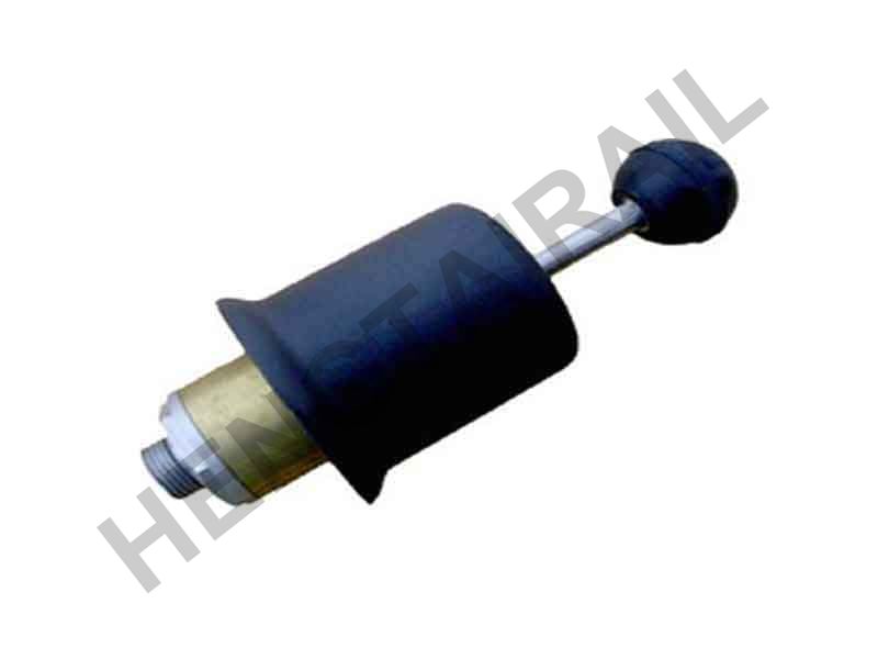
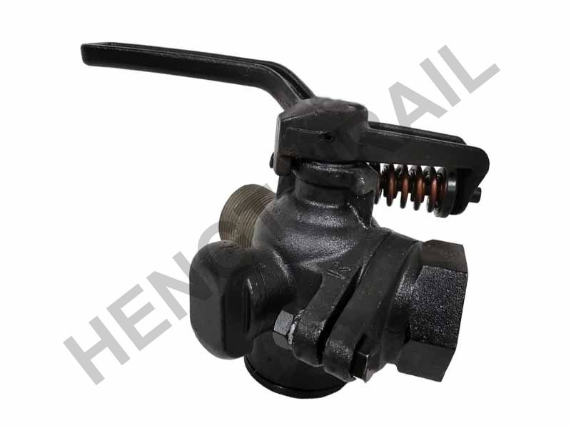
Caboose valve is also named emergency brake valve, which is installed in the caboose. It is used to apply emergency brake by the driver when the train is in an emergent condition threatening the traffic safety.
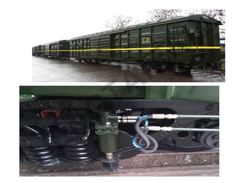
MUB air brake system was developed according to UIC standard, and the technical parameters and interface sizes can meet the requirements of UIC standard, which makes sure that the vehicles mounting MUB air brake system can operate with the vehicles mounting other UIC standard brake system (eg. the vehicles installing Knorr or Wabtec brake system).
The MUB brake system is fully compliant with UIC standards and got the TSI certificate in 2013 and is on the ERA (Eu Railways) database.
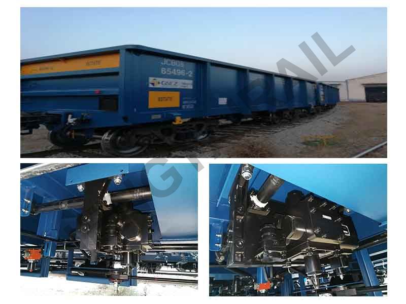
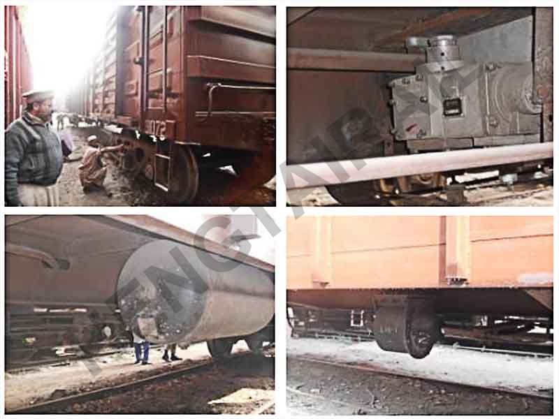
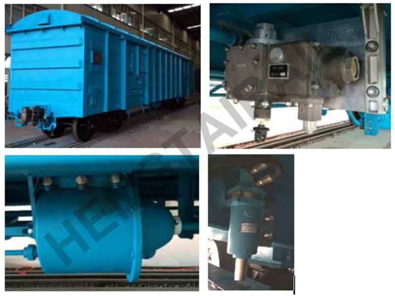
MUB brake system include: distributor valve, sensor valve, brake cylinder, auxiliary reservoir, bidirectional slack adjuster, throttle , angle cock, hose coupling, etc.
MUB brake system has been used in Pakistan, Sudan, Myanmar and Gabon since 2009 with stable and good performance.
The parameters of MUB air brake system are designed based on UIC standard, and IRIS Quality Management System is strictly followed during our R & D process, so as to ensure the performance and the reliability of the products.
Performance Parameter | Requirements Of UIC Standard | MUB Brake System | |
Working temperature scope (℃) | -40~70 | -40~70 | |
Nominal pressure(kPa) | 500±10 | 500±10 | |
Maximum pressure of brake cylinder (kPa) | Loaded status | 380±10 | 380±10 |
Empty status | According to client’s requirements | ||
Time for the brake cylinder pressure to rise from 0 to 95% of the maximum pressure(s) | Position G | 18~30 | 24±3 |
Position P |
3~6 | 3~6 | |
Time for the brake cylinder pressure to drop from the maximum pressure to 40kPa(s) | Position G | 45~60 | 45~60 |
Position P | 15~20 | 15~20 | |
Braking propagation speed (m/s) | ≥250 | The maximum speed is 285 | |


