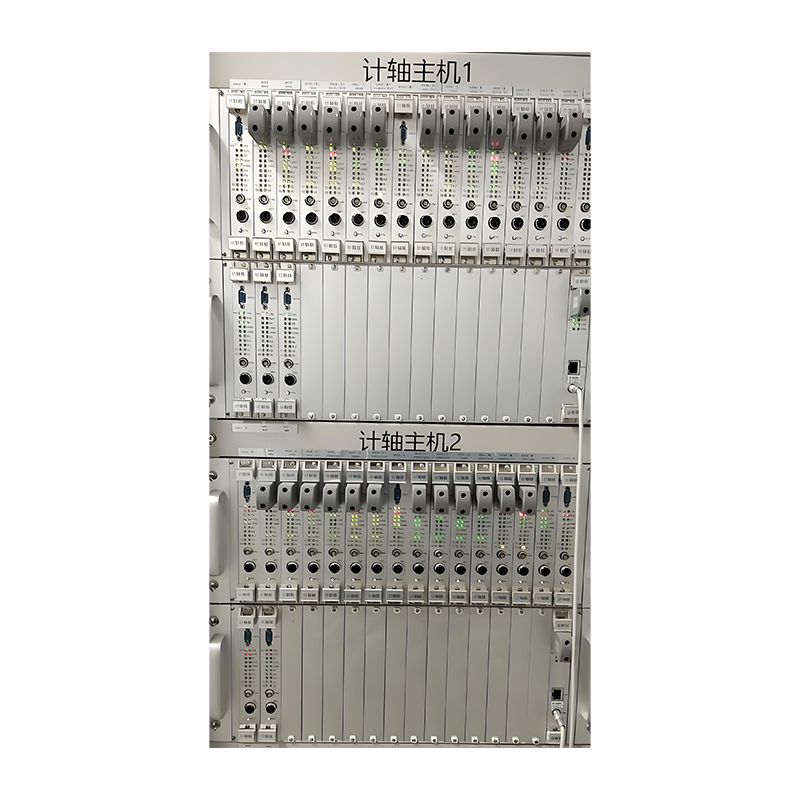
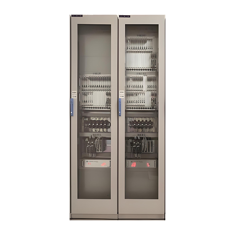
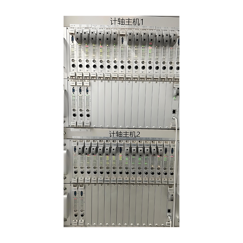
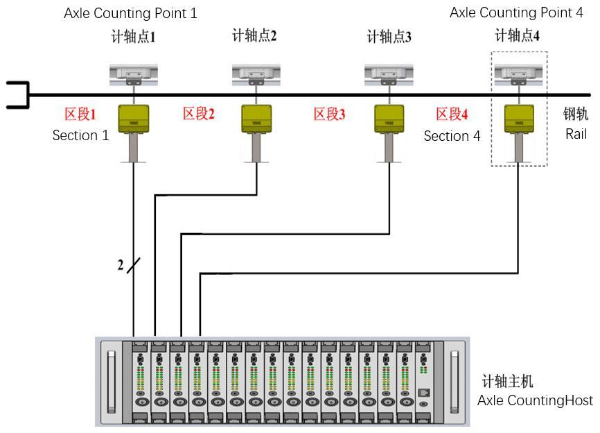
The axle counting cabinet, which houses the main axle counting unit and is installed indoors in the equipment room. The unit consists of axle counting boards and diagnostic boards. The axle counting boards are responsible for detecting the occupied/ clear status of track sections and interfacing with the computer-based interlocking system. The diagnostic boards perform system diagnostics and provide an interface with the centralized monitoring system.
Power Type | Current Requirement | Power Supply Target |
AC 220V Power 1 | 3A | Powers the indoor axle counting host |
AC 220V Power 2 | 3A | Powers the indoor axle counting host |
DC 120V Power 1 | 5A | Powers outdoor axle counting points (only for A1) |
DC 120V Power 2 | 5A | Powers outdoor axle counting points (only for A1) |
DC 24V Power | 2A | Powers track relays and reset input |
· A single host unit can manage up to 31 track sections.
· One cabinet can accommodate up to two host units, connecting 62 outdoor axle counting points and controlling 62 track sections.
· Each track section can be configured with up to 16 outdoor axle counting points.
· Host unit boards support hot-swappable operation.
· The connection cable between each host and outdoor axle counter uses 2-core or 4-core wires.
· A star topology is used for both indoor and outdoor connections.
· Cabinet dimensions, color codes, and other specifications can be customized upon request; the standard dimensions are 2250 mm (H) × 600 mm (W) × 800 mm (D).
